Winding Inductance And Transformers . Operating at high frequency presents unique problems in the design of transformers to minimize the effect of winding capacitance. The primary winding receives the input signal, and the secondary winding generates the output signal. A transformer consists of two electrically isolated coils and operates on faraday’s principal of “mutual induction”, in which an emf is induced in the transformers secondary coil by. The transformer in the figure above is intended to provide both high and low voltages necessary in an. The two inductors in a transformer are called windings. The unpowered inductor in a transformer is called the secondary winding. With winding factors as defined here and in the sections below, it is possible to define winding inductances. As shown in figure 1,. The powered inductor in a transformer is called the primary winding.
from www.rakeshtransformers.com
The primary winding receives the input signal, and the secondary winding generates the output signal. A transformer consists of two electrically isolated coils and operates on faraday’s principal of “mutual induction”, in which an emf is induced in the transformers secondary coil by. The transformer in the figure above is intended to provide both high and low voltages necessary in an. The two inductors in a transformer are called windings. The unpowered inductor in a transformer is called the secondary winding. Operating at high frequency presents unique problems in the design of transformers to minimize the effect of winding capacitance. With winding factors as defined here and in the sections below, it is possible to define winding inductances. The powered inductor in a transformer is called the primary winding. As shown in figure 1,.
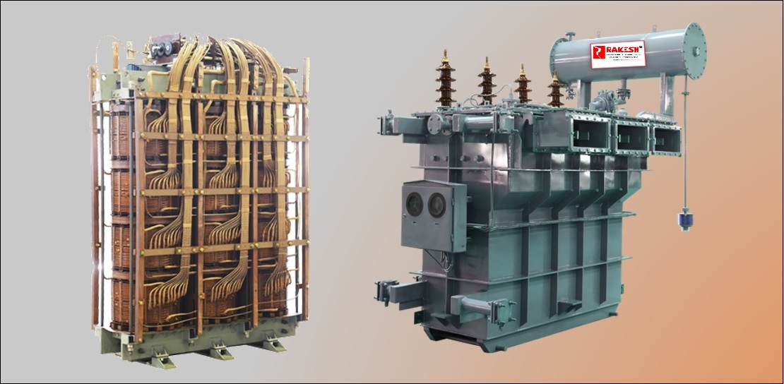
Solar 3/4 Winding Transformer Rakesh Transformers
Winding Inductance And Transformers Operating at high frequency presents unique problems in the design of transformers to minimize the effect of winding capacitance. Operating at high frequency presents unique problems in the design of transformers to minimize the effect of winding capacitance. The two inductors in a transformer are called windings. The primary winding receives the input signal, and the secondary winding generates the output signal. A transformer consists of two electrically isolated coils and operates on faraday’s principal of “mutual induction”, in which an emf is induced in the transformers secondary coil by. The powered inductor in a transformer is called the primary winding. As shown in figure 1,. The unpowered inductor in a transformer is called the secondary winding. With winding factors as defined here and in the sections below, it is possible to define winding inductances. The transformer in the figure above is intended to provide both high and low voltages necessary in an.
From www.electricaltechnology.org
Dot Convention & Notation in a Transformer Phasing & Polarity Winding Inductance And Transformers Operating at high frequency presents unique problems in the design of transformers to minimize the effect of winding capacitance. The unpowered inductor in a transformer is called the secondary winding. The two inductors in a transformer are called windings. The transformer in the figure above is intended to provide both high and low voltages necessary in an. With winding factors. Winding Inductance And Transformers.
From studylib.net
ThreePhase Transformer Inductance Matrix Type (Two Windings) Winding Inductance And Transformers Operating at high frequency presents unique problems in the design of transformers to minimize the effect of winding capacitance. The two inductors in a transformer are called windings. The powered inductor in a transformer is called the primary winding. A transformer consists of two electrically isolated coils and operates on faraday’s principal of “mutual induction”, in which an emf is. Winding Inductance And Transformers.
From www.istockphoto.com
Toroidal Inductor With Copper Wire Winding Transformer And Electric Winding Inductance And Transformers As shown in figure 1,. The two inductors in a transformer are called windings. Operating at high frequency presents unique problems in the design of transformers to minimize the effect of winding capacitance. The powered inductor in a transformer is called the primary winding. With winding factors as defined here and in the sections below, it is possible to define. Winding Inductance And Transformers.
From www.physicsforums.com
Transformer inductance a function of mu only? Winding Inductance And Transformers With winding factors as defined here and in the sections below, it is possible to define winding inductances. As shown in figure 1,. The primary winding receives the input signal, and the secondary winding generates the output signal. The powered inductor in a transformer is called the primary winding. A transformer consists of two electrically isolated coils and operates on. Winding Inductance And Transformers.
From itecnotes.com
Electronic Current in Transformer Primary (Forward Converter Winding Inductance And Transformers With winding factors as defined here and in the sections below, it is possible to define winding inductances. The primary winding receives the input signal, and the secondary winding generates the output signal. The two inductors in a transformer are called windings. Operating at high frequency presents unique problems in the design of transformers to minimize the effect of winding. Winding Inductance And Transformers.
From www.gotrend.com.tw
What is transformer leakage inductance? What is sandwich winding Winding Inductance And Transformers The transformer in the figure above is intended to provide both high and low voltages necessary in an. The two inductors in a transformer are called windings. As shown in figure 1,. The powered inductor in a transformer is called the primary winding. Operating at high frequency presents unique problems in the design of transformers to minimize the effect of. Winding Inductance And Transformers.
From perschools.weebly.com
Smps transformer winding calculation perschools Winding Inductance And Transformers The unpowered inductor in a transformer is called the secondary winding. The two inductors in a transformer are called windings. With winding factors as defined here and in the sections below, it is possible to define winding inductances. The powered inductor in a transformer is called the primary winding. The transformer in the figure above is intended to provide both. Winding Inductance And Transformers.
From www.analogictips.com
Mutual inductance & transformers when EMF EMI Winding Inductance And Transformers Operating at high frequency presents unique problems in the design of transformers to minimize the effect of winding capacitance. As shown in figure 1,. The primary winding receives the input signal, and the secondary winding generates the output signal. The transformer in the figure above is intended to provide both high and low voltages necessary in an. A transformer consists. Winding Inductance And Transformers.
From www.coilwindingmachines.eu
Toroid Winding Machine for small transformers, inductors, chokes and Winding Inductance And Transformers As shown in figure 1,. The transformer in the figure above is intended to provide both high and low voltages necessary in an. The primary winding receives the input signal, and the secondary winding generates the output signal. Operating at high frequency presents unique problems in the design of transformers to minimize the effect of winding capacitance. The powered inductor. Winding Inductance And Transformers.
From www.youtube.com
Mutual inductance versus transformer the power electronics perspective Winding Inductance And Transformers The transformer in the figure above is intended to provide both high and low voltages necessary in an. With winding factors as defined here and in the sections below, it is possible to define winding inductances. The primary winding receives the input signal, and the secondary winding generates the output signal. Operating at high frequency presents unique problems in the. Winding Inductance And Transformers.
From www.rakeshtransformers.com
Solar 3/4 Winding Transformer Rakesh Transformers Winding Inductance And Transformers As shown in figure 1,. The two inductors in a transformer are called windings. The unpowered inductor in a transformer is called the secondary winding. The transformer in the figure above is intended to provide both high and low voltages necessary in an. With winding factors as defined here and in the sections below, it is possible to define winding. Winding Inductance And Transformers.
From electricalacademia.com
Equivalent Circuit of Transformer Referred to Primary and Secondary Winding Inductance And Transformers The powered inductor in a transformer is called the primary winding. As shown in figure 1,. With winding factors as defined here and in the sections below, it is possible to define winding inductances. The two inductors in a transformer are called windings. Operating at high frequency presents unique problems in the design of transformers to minimize the effect of. Winding Inductance And Transformers.
From www.plantautomation-technology.com
FLAT WIRE INDUCTORS WINDING RANGE POWER & DISTRIBUTION TRANSFORMERS Winding Inductance And Transformers The unpowered inductor in a transformer is called the secondary winding. As shown in figure 1,. The transformer in the figure above is intended to provide both high and low voltages necessary in an. The powered inductor in a transformer is called the primary winding. Operating at high frequency presents unique problems in the design of transformers to minimize the. Winding Inductance And Transformers.
From www.slideserve.com
PPT Leakage Impedance of Transformer Windings PowerPoint Presentation Winding Inductance And Transformers The primary winding receives the input signal, and the secondary winding generates the output signal. As shown in figure 1,. The unpowered inductor in a transformer is called the secondary winding. The powered inductor in a transformer is called the primary winding. A transformer consists of two electrically isolated coils and operates on faraday’s principal of “mutual induction”, in which. Winding Inductance And Transformers.
From www.slideserve.com
PPT Leakage Impedance of Transformer Windings PowerPoint Presentation Winding Inductance And Transformers With winding factors as defined here and in the sections below, it is possible to define winding inductances. The primary winding receives the input signal, and the secondary winding generates the output signal. A transformer consists of two electrically isolated coils and operates on faraday’s principal of “mutual induction”, in which an emf is induced in the transformers secondary coil. Winding Inductance And Transformers.
From www.amprion.net
Transformer Winding Inductance And Transformers Operating at high frequency presents unique problems in the design of transformers to minimize the effect of winding capacitance. The two inductors in a transformer are called windings. The unpowered inductor in a transformer is called the secondary winding. The transformer in the figure above is intended to provide both high and low voltages necessary in an. The powered inductor. Winding Inductance And Transformers.
From itecnotes.com
Transformer Calculating Inductance Values from Transformer Datasheet Winding Inductance And Transformers The unpowered inductor in a transformer is called the secondary winding. The primary winding receives the input signal, and the secondary winding generates the output signal. As shown in figure 1,. A transformer consists of two electrically isolated coils and operates on faraday’s principal of “mutual induction”, in which an emf is induced in the transformers secondary coil by. The. Winding Inductance And Transformers.
From www.lafisicayquimica.com
Inductancia mutua La fisica y quimica Winding Inductance And Transformers The powered inductor in a transformer is called the primary winding. The two inductors in a transformer are called windings. The transformer in the figure above is intended to provide both high and low voltages necessary in an. A transformer consists of two electrically isolated coils and operates on faraday’s principal of “mutual induction”, in which an emf is induced. Winding Inductance And Transformers.